


Description
Simpson Strong-Tie hurricane ties provide a positive connection between the truss/rafter and the wall of the structure to resist wind and seismic forces.
Material
- See table
Finish
- Galvanized. H7Z and H11Z — ZMAX® coating. Some models available in stainless steel or ZMAX. See Corrosion Information.
Installation
- Use all specified fasteners; see General Notes.
- Hurricane ties can be installed with flanges facing inward or outward.
- H2.5T, H3 and H6 ties are shipped in equal quantities of right and left versions (right versions shown).
- Hurricane ties do not replace solid blocking.
- When installing ties on plated trusses (on the side opposite the truss plate), do not fasten through the truss plate from behind. This can force the truss plate off of the truss and compromise truss performance.
- H10A optional nailing to connect shear blocking: use 0.131" x 2 1/2" nails. Slots allow maximum field bending up to a pitch of 6:12; use H10A sloped loads for field-bent installation.
Load Tables
Load Values with Carbon Steel Nails
These products are available with additional corrosion protection. Additional products on this page may also be available with this option, check with Simpson Strong-Tie for details.
For stainless-steel fasteners, see Fastener Types and Sizes Specified for Simpson Strong-Tie Connectors.
Many of these products are approved for installation with Strong-Drive® SD Connector screws.
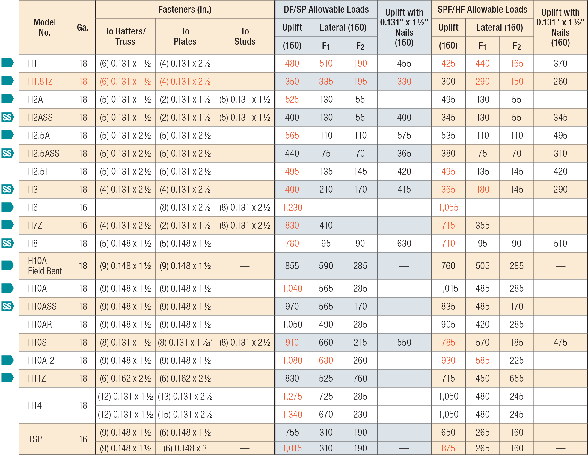
- See General Notes for Straps and Ties.
- Allowable loads are for one anchor. A minimum rafter thickness of 2 1/2" must be used when framing anchors are used on each side of the joist and on the same side of the plate (exception: connectors installed such that nails on opposite side don't interfere).
- Allowable DF/SP uplift load for stud-to-bottom plate installation (see detail 15) is 390 lb. (H2.5A); 265 lb. (H2.5ASS); and 310 lb. (H8). For SPF/HF values, multiply these values by 0.86.
- Allowable loads in the F1 direction are not intended to replace diaphragm boundary members or cross-grain bending of the truss or rafter members.
- When cross-grain bending or cross-grain tension cannot be avoided in the members, mechanical reinforcement to resist such forces shall be considered by the Designer.
- Hurricane ties are shown on the outside of the wall for clarity and assume a minimum overhang of 3 1/2". Installation on the inside of the wall is acceptable (see General Instructions for the Installer notes). For uplift continuous load path, install connectors in the same area (e.g., truss-to-plate connector and plate-to-stud connector) on the same side of the wall, unless detailed by designer. See technical bulletin T-C-HTIECON for more information.
- Southern pine allowable uplift loads for H10A = 1,340 lb. and for the H14 = 1,465 lb.
- Refer to Simpson Strong-Tie® technical bulletin T-C-HTIEBEAR for allowable bearing enhancement loads.
- H10S can have the stud offset a maximum of 1" from the rafter (center to center) for a reduced uplift of 890 lb. (DF/SP) and 765 lb. (SPF).
- H10S nails to plates are optional for uplift but required for lateral loads.
- Some load values for the stainless-steel connectors shown here are lower than those for the carbon-steel versions. Ongoing test programs have shown this also to be the case with other stainless-steel connectors in the product line that are installed with nails. See General Corrosion Risks for updated information.
- The allowable loads of stainless-steel connectors match carbon-steel connectors when installed with stainless-steel Strong-Drive® SCNR Ring-Shank Connector nails. For more information, refer to engineering letter L-F-SSNAILS.
- Allowable DF/SP/SPF uplift load for the H2.5A fastened to a 2x4 truss bottom chord and double top plates using (5) 0.131" x 1 1/2" nails in the top plates and (3) 0.131" x 1 1/2" nails in the lowest three flange holes into the truss bottom chord is 260 lb. (160).
- For TSP installed stud to single plate see Stud-Plate Ties.
- Fasteners: Nail dimensions in the table are listed diameter by length. For additional information, see Fastener Types and Sizes Specified for Simpson Strong-Tie Connectors.
| Model No. | Fasteners | DF/SP Allowable Loads | Uplift with 8d x 1 1/2" Nails (160) | SPF/HF Allowable Loads | Uplift with 8d x 1 1/2" Nails (160) | ||||||
|---|---|---|---|---|---|---|---|---|---|---|---|
| To Rafters/ Truss | To Plates | To Studs | Uplift | Lateral (160) | Uplift | Lateral (160) | |||||
| (160) | F1 | F2 | (160) | F1 | F2 | ||||||
|
|||||||||||
| H2.5ASS | 5-SS8d | 5-SS8d | - | 440 | 75 | 70 | 365 | 380 | 75 | 70 | 310 |
| 5-SSA8d | 5-SSA8d | - | 600 | 110 | 110 | 575 | 535 | 110 | 110 | 495 | |
| H3SS | 4-SS8d | 4-SS8d | - | 280 | 145 | 120 | 275 | 225 | 100 | 85 | 210 |
| 4-SSA8d | 4-SSA8d | - | 455 | 125 | 160 | 415 | 320 | 105 | 140 | 290 | |
| H8SS | 5-SSN10 | 5-SSN10 | - | 610 | 90 | 120 | 440 | 370 | 90 | 55 | 335 |
| 5-SSNA10 | 5-SSNA10 | - | 745 | 75 | - | 630 | 565 | 75 | - | 510 | |
| Model No. | Fasteners | DF/SP Allowable Loads | SPF/HF Allowable Loads | ||||||||
|---|---|---|---|---|---|---|---|---|---|---|---|
| To Rafters/ Truss | To Plates/ Base | To Studs/ Post | Uplift | Lateral | Uplift | Lateral | |||||
| (160) | F1 (160) | F2 (160) | (160) | F1 (160) | F2 (160) | ||||||
|
These products are available with additional corrosion protection. Additional products on this page may also be available with this option, check with Simpson Strong-Tie for details.
|
|||||||||||
| H1 | 6-SD9112 | 4-SD9112 | - | 505 | 600 | 390 | 435 | 515 | 335 | ||
| H2.5 | 5-SD9112 | 5-SD9112 | - | 480 | 305 | 165 | 410 | 265 | 145 | ||
| H2.5A | 5-SD9112 | 5-SD9112 | - | 625 | 450 | 110 | 540 | 385 | 95 | ||
| H8 | 5-SD9112 | 5-SD9112 | - | 820 | 85 | - | 705 | 75 | - | ||
| H10 | 8-SD9112 | 8-SD9112 | - | 1135 | 840 | 325 | 975 | 720 | 280 | ||
Extra Information
Brand:
Simpson Strong-Tie
Weight:
0.40 LBS


")

