


")
")
")
")


Description
Purlin anchors offer solutions for wood-to-concrete and concrete-block connections which satisfy code requirements. The HPA offers the highest capacity in concrete. The PA’s dual-embedment line allows installation in concrete or concrete block.
Material
- PA — 12 gauge; HPA — 10 gauge
Finish
- Galvanized; PAs available in HDG or ZMAX® coating
Installation
- Use all specified fasteners; some models have extra fastener holes. See General Notes.
- Purlin anchor must hook around rebar.
- Allowable loads are for a horizontal installation into the side of a concrete or masonry wall.
- Strap may be bent one full cycle (bent vertical 90° then bent horizontal).
- PA51/PA68 — for additional length, an MST strap can be attached using 1/2" bolts through existing holes.
- Refer to technical bulletin PA Foundation Straps for Uplift Resistance (T-PAUPLIFT) for additional information.
Edge Distance — minimum concrete edge distance is 5". Minimum concrete block left-to-right edge distance is 20".
Concrete Block Wall — the minimum wall specifications are:
A — one # 4 vertical rebar, 32" long, 16" each side of anchor
B — two courses of grout-filled block above and below the anchor (no cold joints allowed)
C — a horizontal bond beam with two #4 rebars, 40" long, a maximum of two courses above or below the anchor
D — minimum masonry compressive strength, f'm = 1,500 psi
Options
- See LTT, HTT and S/LTT, S/DTT tension ties for alternate retrofit solutions
Codes
ASCE 7-10 12.11.2.2.5 states:
... Diaphragm to structural wall anchorage using embedded straps shall be attached to, or hooked around the reinforcing steel or otherwise terminated so as to effectively transfer forces to the reinforcing steel.
Load Tables
These products are available with additional corrosion protection. Additional products on this page may also be available with this option, check with Simpson Strong-Tie for details.
| Max. Ledger Size | Model No. | Strap Length, L (in.) | Embed Length, le (in.) | Uncracked Concrete | Cracked Concrete | GFCMU Wall | Max. Allowable Strap Tension | Deflection at Allowable Load (in.) | ||||
|---|---|---|---|---|---|---|---|---|---|---|---|---|
| Concrete | GFCMU | Required Nails (in.) | Tension | Required Nails (in.) | Tension | Required Nails (in.) | Tension | |||||
| 4x Ledger | PA18 | 18 1/2 | 4 | 6 | (12) 0.148 x 3 | 2,430 | (12) 0.148 x 3 | 2,260 | (12) 0.148 x 3 | 1,890 | NA | 0.087 |
| PA23 | 23 3/4 | 4 | 6 | (16) 0.148 x 3 | 3,220 | (12) 0.148 x 3 | 2,260 | (16) 0.148 x 3 | 2,815 | NA | 0.118 | |
| PA28 | 29 | 4 | 6 | (16) 0.148 x 3 | 3,230 | (12) 0.148 x 3 | 2,260 | (16) 0.148 x 3 | 2,815 | NA | 0.085 | |
| PA35 | 35 | 4 | 6 | (16) 0.148 x 3 | 3,230 | (12) 0.148 x 3 | 2,260 | (16) 0.148 x 3 | 2,815 | NA | 0.085 | |
| HPA28 | 32 1/2 | 6 | 6 | (22) 0.148 x 3 | 5,145 | (20) 0.148 x 3 | 4,675 | — | — | NA | 0.133 | |
| HPA35 | 38 1/2 | 8 1/4 | 8 1/4 | (22) 0.148 x 3 | 5,145 | (22) 0.148 x 3 | 5,145 | — | — | NA | 0.132 | |
See Footnotes1 below
| Max. Ledger Size | Model No. | Strap Length, L (in.) | Embed Length, le (in.) | Uncracked Concrete | Cracked Concrete | GFCMU Wall | Max. Allowable Strap Tension | Deflection at Allowable Load (in.) | ||||
|---|---|---|---|---|---|---|---|---|---|---|---|---|
| Concrete | GFCMU | Required Nails (in.) | Tension | Required Nails (in.) | Tension | Required Nails (in.) | Tension | |||||
| 4x Ledger | PA18 | 18 1/2 | 4 | 6 | (12) 0.148 x 3 | 2,430 | (12) 0.148 x 3 | 1,980 | (12) 0.148 x 3 | 1,890 | 3,220 | 0.087 |
| PA23 | 23 3/4 | 4 | 6 | (14) 0.148 x 3 | 2,830 | (12) 0.148 x 3 | 1,980 | (16) 0.148 x 3 | 2,815 | 3,220 | 0.118 | |
| PA28 | 29 | 4 | 6 | (14) 0.148 x 3 | 2,830 | (12) 0.148 x 3 | 1,980 | (16) 0.148 x 3 | 2,815 | 3,935 | 0.085 | |
| PA35 | 35 | 4 | 6 | (14) 0.148 x 3 | 2,830 | (12) 0.148 x 3 | 1,980 | (16) 0.148 x 3 | 2,815 | 3,935 | 0.085 | |
| HPA28 | 32 1/2 | 6 | 6 | (22) 0.148 x 3 | 5,145 | (20) 0.148 x 3 | 4,090 | — | — | 5,145 | 0.133 | |
| HPA35 | 38 1/2 | 8 1/4 | 8 1/4 | (22) 0.148 x 3 | 5,145 | (22) 0.148 x 3 | 5,145 | — | — | 5,145 | 0.132 | |
Footnotes1
- Allowable loads have been increased for wind or earthquake loading with no further increase allowed. Reduce where other loads govern.
- Deflection listed is at the highest allowable load.
- To obtain LRFD values, multiply ASD seismic load values by 1.4 and wind load values by 1.67 (1.6 for 2012 IBC).
- Nail quantities are based on Douglas fir (DF) or equivalent specific gravity of 0.50 or better. For use in spruce-pine-fir (SPF) or hem fir (HF), nails quantities shall be increased by 1.15 to achieve loads listed.
- For wall anchorage systems in SDC C-F, the maximum strap allowable load shall not be less than 1.4 times the ASD anchor design load.
- Minimum center-to-center spacing is 3x the required embedment — i.e., standard installation is based on a minimum 5" end distance.
- Structural composite lumber beams have sides that show either the wide face or the lumber strands/veneers. Values in the tables reflect installation into the wide face.
- Concrete shall have a minimum compressive strength of f'c = 3,000 psi.
- Grout-filled CMU (GFCMU) shall have a minimum compressive strength of f'm = 1,500 psi.
- PA models installed vertically in the top of a grouted masonry wall with 6" embedment and (12) 0.148" x 3" nails achieve an allowable uplift load of 1,890 lb.
- For PA models, 0.148" x 1 1/2" nails may be substituted for 0.148" x 3" nails at 100% of listed load and with a 15% increase in deflection. For installation over sheathing, use 3"-long nails minimum.
- Fasteners: Nail dimensions in the table are listed diameter by length. For additional information, see Fastener Types and Sizes Specified for Simpson Strong-Tie Connectors.
These products are available with additional corrosion protection. Additional products on this page may also be available with this option, check with Simpson Strong-Tie for details.
Many of these products are approved for installation with Strong-Drive® SD Connector screws.
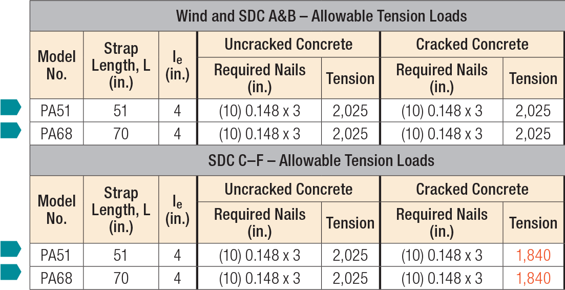
- Allowable loads have been increased for wind or earthquake loading with no further increase allowed. Reduce where other loads govern.
- Concrete shall have a minimum compressive strength of f'c = 2,500 psi.
- Masonry applications require grout-filled CMU with minimum compressive strength of f'm = 1,500 psi.
- Deflection at highest allowable load is as follows: PA51 and PA68 = 0.10".
- PA allowable lateral loads are F1 = 795 lb. and F2 = 280 lb.
- Strong-Drive® SD9 x 1 1/2" Connector screws may be substituted for table fasteners with no load reduction.
- Fasteners: Nail dimensions in the table are listed diameter by length. For additional information, see Fastener Types and Sizes Specified for Simpson Strong-Tie Connectors.
Extra Information
Warranty Information
Please View Warranty Page For More Info
")


