


Description
The SDWS Framing screw is designed and load-rated for replacing 16d, 10d and 8d nails in framing applications. The SDWS Framing screw is 0.160" in diameter and superior to nails in holding power and pull-out resistance. It is code listed under IAPMO UES ER-192 and meets 2015 and 2018 IRC® and IBC® code requirements for several common wood framing applications.
The screw has a SawTooth™ point that makes for fast installations with reduced torque without predrilling, and its specially designed head countersinks easily to provide a clean, flush finish. The T25 bit holds the 6-lobe recess tightly, reducing cam-out and head stripping.
Key Features
- Large washer head with underhead box-nibs provides increased bearing in structural applications and provides clean and easy countersinking (0.44" head dia.)
- SawTooth point ensures fast starts, reduces installation torque and eliminates the need for predrilling in most applications
- The 6-lobe drive provides positive bit engagement resulting in easier installations and longer bit life
- Quik Guard® coating provides protection in indoor and outdoor applications
- US Patent 9,523,383
Applications
- Multipurpose wood-to-wood and engineered-wood applications, including framing, indoor/outdoor projects
Product Includes
- Driver bit BIT25T-2
Load Tables
SDWS Framing Screw — Allowable Shear Loads for Sawn Lumber
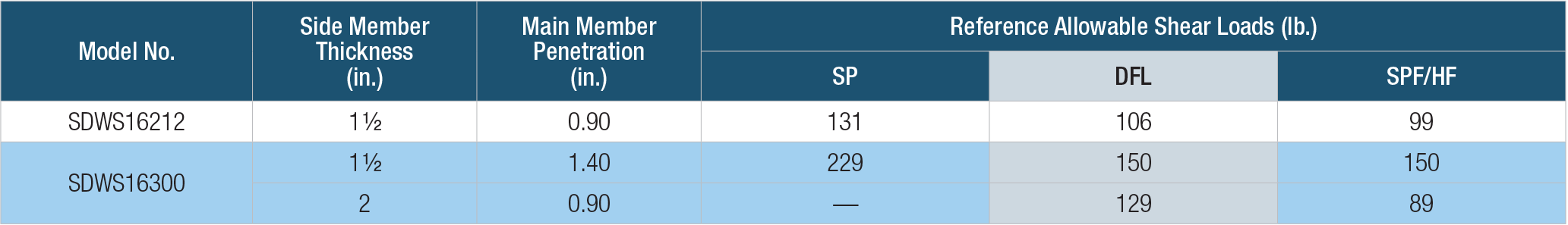
- All applications are based on full penetration into the main member. Full penetration is the screw length minus the side member thickness.
- Allowable loads are shown at the wood load duration factor of CD = 1.0. Loads may be increased for load duration per the building code up to a CD = 1.6. Tabulated values must be multiplied by all applicable adjustment factors per the NDS.
- Minimum fastener spacing requirements to achieve table loads; 2" (SDWS16212) and 3" (SDWS16300) end distance, 1/2" (SDWS16212) and 1" (SDWS16300) edge distance, 7/16" between staggered rows of fasteners, 1" between non-staggered and 4" between fasteners in a row.
- For in-service moisture content greater than 19% use CM = 0.70.
- Screws must be installed straight into the side grain of the wood main member with the screw axis at a 90°-angle to the wood fibers.
SDWS Framing Screw — Allowable Withdrawal Load in Sawn Lumber
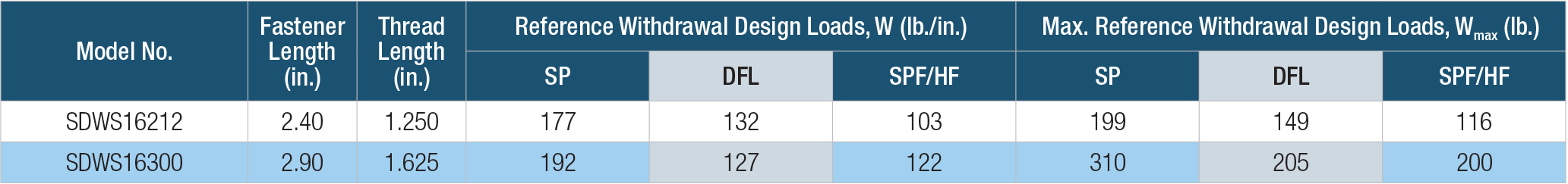
- The tabulated reference withdrawal design values (W) are in pounds per inch of the thread penetration into the main member.
- The tabulated reference withdrawal design values (Wmax) are in pounds where the entire thread length must penetrate into the main member.
- Tabulated reference withdrawal design values (W) and (Wmax) are shown at a CD = 1.0. Loads may be increased for load duration per the building code up to a CD = 1.6. Tabulated values must be multiplied by all applicable adjustment factors from the NDS as referenced in the IBC or IRC.
- Values are based on the lesser of withdrawal from the main member or pull-through of a 1 1/2" side member. For in-service moisture content greater than 19% use CM = 0.65.
SDWS Framing Screw — Allowable Shear Loads for Wood Structural Panel Side Member
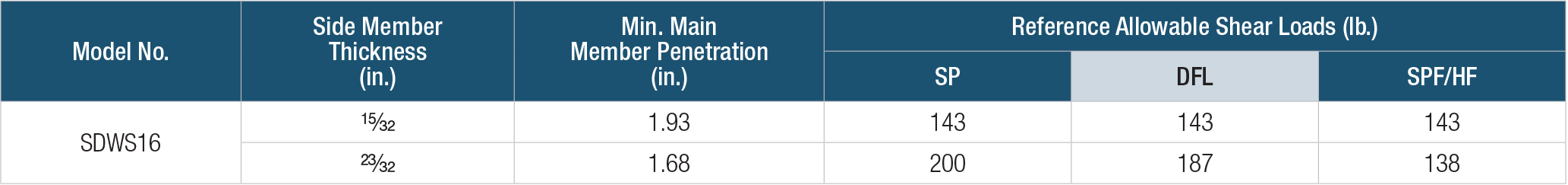
- Allowable loads are shown at the wood load duration factor of CD=1.0. Loads may be increased for load duration per the building code up to a CD=1.6. Tabulated loads must be multiplied by all applicable adjustment factors per the NDS.
- WSP side members for tests was oriented strand board (equivalent specfic gravity = 0.50).
- All applications are based on full penetration into the main member. Full penetration is the screw length minus the side member thickness.
- Screws must be installed straight into the side grain of the wood main member with the screw axis at a 90°-angle to the wood fibers.
SDWS Framing Screw — Allowable Pull-Through Loads for Wood Structural Panel Side Member

- Allowable loads are shown at the wood load duration factor pf CD=1.0. Loads may be increased for load duration per the building code up to a CD=1.6. Tabulated loads must be multiplied by all applicable adjustment factors per the NDS.
- WSP side members for tests was oriented strand board (equivalent specfic gravity = 0.50).
- For connections with 15/32" and 23/32" thick OSB side members, the lesser of withdrawal loads from the main and pull-through loads from WSP side member shall be used in design.
See additional Load Tables, Technical Data and Installation Instructions for the Strong-Drive® SDWS Framing screw


")
